


Education: Influence of Layout Constraints in Topology Optimization
The spatial arrangement of materials, also known as layout problem in literature, is vital a issue for the design and usability of many engineering products. Specifically, in building design, the manner in which material is distributed is significant for engineers to develop a lateral bracing system or create a conceptual design for structural members. Although, topology optimization is a very powerful tool for design, often the resulting topologies produced consist of complex geometries and poor material layout which are of little value to real-world problems due to expense and ease of manufacturing.
An example of a typical topology optimization result progressively applying manufacturing constraints is shown below. In order to make the results more significant from an engineering perspective, several constraints should be imposed. Click the buttons below to view the result with different imposed constraints. A discussion of the results with the imposed constraints enforced is below.
Problem Description
No Constraints

Projection Constraint
Add Symmetry Constraint
Add Pattern Repetition
Add Pattern Gradation
Actual Building
Problem Description
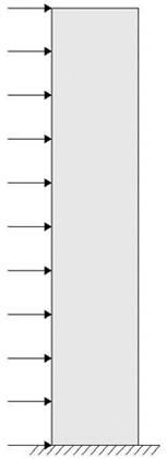
The prototypical problem for the design of a high rise building is the problem of a vertical cantilever beam fixed at the top of the foundation. The fundamental laws of mechanics controlling such a problem are rather simple, being that the problem is statically determinate, yet very powerful. Thus, we study the problem illustrated here subject to a uniform wind load to understand the high-rise behavior.
No Constraints
The result presented here shows topology optimization over a mesh of four node quadrilateral elements (Q4). However, a common issue associated with the Q4 implementation is the appearance of checkerboarding, a numerical phenomenon of alternating regions of void and solid material. Since this phenomenon overestimates the stiffness of a region or patch of elements, theses patches are numerically advantageous and appear frequently in the topology optimization results, giving rise to the necessity for an additional constraint.
Projection Constraint
With the additional projection constraint, the density or sensitivity of each element is computed as a weighted average of the element and its closest neighbors (shown here). Since these techniques are often dependent on the refinement of the mesh, a fixed length scale (minimum member size), is specified for the overall design domain to achieve mesh-independent results.
After adding the projection constraint to eliminate checkerboarding and specify a minimum member size, the results begin to resemble a bracing system. However, the results can be made more practical to architects and engineers through the addition of a constraint on the symmetry of the design.
After adding the projection constraint to eliminate checkerboarding and specify a minimum member size, the results begin to resemble a bracing system. However, the results can be made more practical to architects and engineers through the addition of a constraint on the symmetry of the design.
Add Symmetry Constraint
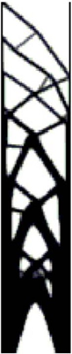
Since the wind can blow from any given direction, the addition of a symmetry constraint is the next logical step to bring the topology optimization results to practical design applications. Thus, the image here shows how the results would change by incorporating a symmetry constraint.
However, in the result shown here, we notice that the majority of the material concentrates at the bottom of the design domain resulting in an uneven distribution of material providing motivation for a pattern repetition constraint.
However, in the result shown here, we notice that the majority of the material concentrates at the bottom of the design domain resulting in an uneven distribution of material providing motivation for a pattern repetition constraint.
Add Pattern Repetition
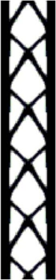
To overcome the concentration of material density at the base of the building with little to no material at the top, we impose a constraint on repeating patterns (periodicity). Within each pattern along the height of the building, the material is a specific fraction of the volume. The result here shows a much more even distribution of material that can be designed by engineers who wish to reuse concrete form work or steel members at each level.
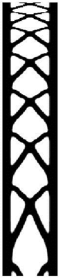
Add Pattern Gradation
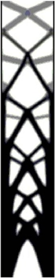
The next logical step is to extend the concept of pattern repetition, or periodic structures, by changing the size and shape of the patterns, a concept known as pattern gradation. By geometrically grading the repeating patterns in a structure, or more specifically in a building, it is possible for structural engineers to come up with a conceptual design for the optimal lateral bracing systems and/or the optimal angles for the diagonal bracing to follow.
From an engineering standpoint, under typical loading conditions, the columns of a building will always be larger in size at its base and smaller towards the top. We introduce the pattern gradation constraint as an effective means to smoothly transition the design from one extreme to another. This concept can be further explored in the context of bracing angles. For example, the lateral design at the top of a high-rise building is controlled by shear loads and the optimal bracing angle is 45°. However, buildings typically suffer from overturning moments, due to wind loads, near the base. Here the bracing angle should be much larger in the range of 65°-70°. Again, the patterns from the base to the top of the building will transition from having a 70° to 75° angle to a 45° angle.
From an engineering standpoint, under typical loading conditions, the columns of a building will always be larger in size at its base and smaller towards the top. We introduce the pattern gradation constraint as an effective means to smoothly transition the design from one extreme to another. This concept can be further explored in the context of bracing angles. For example, the lateral design at the top of a high-rise building is controlled by shear loads and the optimal bracing angle is 45°. However, buildings typically suffer from overturning moments, due to wind loads, near the base. Here the bracing angle should be much larger in the range of 65°-70°. Again, the patterns from the base to the top of the building will transition from having a 70° to 75° angle to a 45° angle.
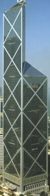
Actual Building
The Bank of China (photo: WorldMarketMedia.com) is one of many examples of a high rise building designed for wind loading. Similar cross bracing is seen along this tower as is predicted by topology optimization with layout constraints applied. The symmetry and repetition in the major bracing is apparent.